
Showing posts with label homebrew. Show all posts
Showing posts with label homebrew. Show all posts
Thursday, 27 January 2022
Tuesday, 3 November 2020
Building a QRPGuys 40/30/20m DSB Digital Transceiver Kit
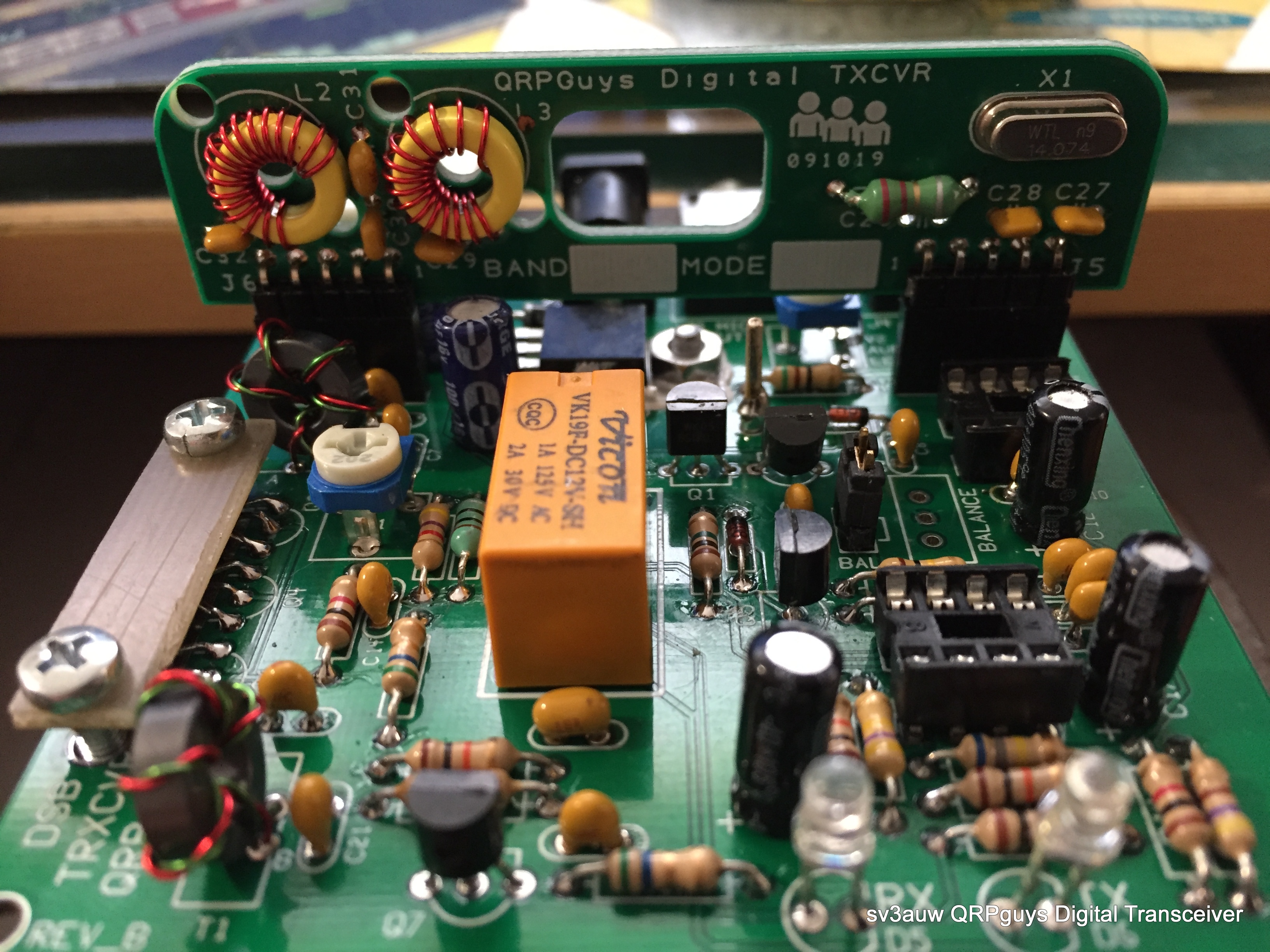
First on the construction bench sat quoting from their site:
"... The QRPGuys DSB Digital Transceiver is a low cost, multiband, DSB transceiver kit, currently with three easy plug-in band modules for 40/30/20m, (additional module pcb’s available). This transceiver is an evolution compiled from various DSB and digital designs on the internet from ZL2BMI, VK3YE, AA7EE, BD6CR, and others. With help from Jim Giammanco, (N5IB) and finally Steve Weber, (KD1JV), we are offering a transceiver with an approximate output of 2.5 watts on 40m, over 1.5 watts on 30m, and over 1 watt on 20m. The receiver sensitivity was measured at .4uV (-115dBm). All the components are included for the main board (3.0″ x 3.12″) and three (40/30/20m) band modules.

The transceiver will run the popular free WSJT-X software (Windows, Linux, or macOS) that requires an accurate time synchronization program, such as Dimension 4, or many of the other free ones available. Users will need two 3.5mm stereo jumpers to your computer or tablet microphone/speaker jacks on the sound card.


The transceiver’s internal VOX circuit will switch to transmit automatically when it senses an audio output signal from the software on the pc or tablet speaker jack. The connections to the transceiver are BNC for the antenna, 3.5mm stereo jumpers to the computer audio jacks, and 12-14 VDC for the pcb mounted 2.1mm pin coaxial power jack. Approximate power consumption is about RX-15mA/TX-350mA. The total weight w/band three modules is 3oz. (85gm). The normal tools required are a soldering iron with a small tip, rosin core solder, and small side cutters. The transceiver can be built in an evening. On a difficulty scale of 1 to 5, 5 being the most difficult, this is rated at 3 depending on your experience. Note also below, plans for building a 3.5″ sq. x 1.0″ high compact chassis from PCB material. ..."

This certain kit is retired now replaced by the Digital Transceiver II kit which has an optional Digital VFO board so the user can choose the Tx frequency and Tx Mode to bands from 160m – 17m.
It can easily constructed in one evening and in my Scale of Difficulty is a fair 2! As long as you are familiar with PCB soldering and toroid cores winding, is a piece of cake!
You can find the old version here but the newer and better is the one I strongly suggest to construct!
The kit I've constructed gave me 4W on 7.074MHz, 2W on 10.136MHz and 1W on 14.074MHz. Definitely not enough power to set alight the Ionosphere but more than enough to have a constant flow of qso's!
Enjoy your time and @staysafe
73 de sv3auw/m0lpt
Friday, 22 May 2020
How much a Kilo weights?!

The homebrew 1Kw dummy Load I've made weights exactly 1.273 grams! That is tad less than 1.3grams per Watt!
It cost me £7 /8€.That is a mere Half Penny or Half Cent per Watt!
Not bad ! Not bad at all!
The actual cost was the purchase of the 4 DL chips 50Ω/250W for a Pound and a Half each from e-bay!
I have a box full of heat sinks bought at a Junk sale night of SARC (Southgate Amateur Radio Club) and I pay also for a copper sheet of 12cm by 50cm another £1.5/2€

Two similar heat sinks MIGed together by my Brother-in-Law along with some drilling and that was it as long as mechanical it takes!
I cut the copper sheet to dimensions(12cm by 20cm) with a Stanley knife, mark and make the thru holes and bolt the chips with the help of 8 M3 bolts applying thermo-paste at the same time!
I connected the chips in series/parallel configuration so I have two rows of 25Ω each connected in parallel for the necessary 50Ω load!

I've built it for myself so I don't think that it needs a box to look better and then my Lin. Amp. tuning is kept short with output power less than the rated 1Kw!
73 de sv3auw/m0lpt

Κατά καιρούς δημοσιεύονται κατασκευές Dummy Loads μεγάλης ισχύος με την διαφορά όμως ότι όταν μπαίνει το κολλητήρι στην πρίζα τα Βατ γίνονται 150 ή 250, όσα ακριβώς αντέχει το ένα μόνο τσιπάκι.
Η κατασκευή είναι απλή.

Ένωσα δύο μεγάλες ψύκτρες με MIG κι αυτό για την καλύτερη θερμική μεταφορά κι επιφάνεια.
Παρέμβαλα ένα φύλο χαλκού για καλύτερη απαγωγή θερμοκρασίας μεταξύ των αντιστάσεων και την αλουμινένιας ψήκτρας και...
και συνέδεσα τις αντιστάσεις ανά δύο σε σειρά και μεταξύ των παράλληλα. 4 x 250 = 1KW!

Ακόμα κι αν δεν αντέχει για μεγάλο χρονικό διάστημα, δεν έχει σημασία διότι δεν θα εκπέμψω με το Dummy Load κι έπειτα δεν έχω τόση ισχύ!
Δεν θα το βάλω σε κουτί παρά θα βρω μόνο έναν τρόπο να στερεώσω τον SO239 κονέκτορα καλύτερα.
Το κόστος των αντιστάσεων δεν ξεπερνά τα 10€ από το e-bay κι ένα φύλο χαλκού δεν θα κοστίσει περισσότερο από 2€. Πραγματικά αξίζει να το προσπαθήσετε κι αν το κάνετε, καλή επιτυχία!
Tuesday, 19 May 2020
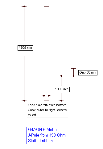
A homemade Slim-Jim antenna for the 6m Band

The Sporadic-E season is starting now so I put in work a 6m Slim Jim antenna I had made last year. Actually it is made for portable use being so flexible and I know that I will not work 6m DXCC with it but it is a honest antenna giving the best it can!

In just two days, yesterday and 2day, I've made FT8 contacts with 25 mostly European Countries, 18 of them confirmed. Mind you that I haven't upload 2nd day's log yet!
No complain at all for 50W and antenna at 10m agl.

I've got the formula or the necessary calculations from the G4AON web page.
https://www.qsl.net/g4aon/j-pole/
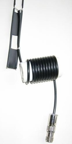
p.s. the wire you might notice is my 160m λ/4 / 80-10 EFHW antenna.

αποδεικνύεται αξιοπρεπέστατη όταν σε μία μέρα, την πρώτη, μου έδωσε 25 χώρες οι 18 επιβεβαιωμένες ήδη!
Ακολουθήστε τις διαστάσεις και καλές επαφές!
https://www.qsl.net/g4aon/j-pole/
Friday, 18 October 2019
Flip-Flop!
Basic flip-Flop a.k.a. Astable Multivibrator, with only 6 components timed at 2.4''.


An enhanced schematic of an A/M!
Tuesday, 31 July 2018
IC-706 FL-100 CW filter installation! So simple!
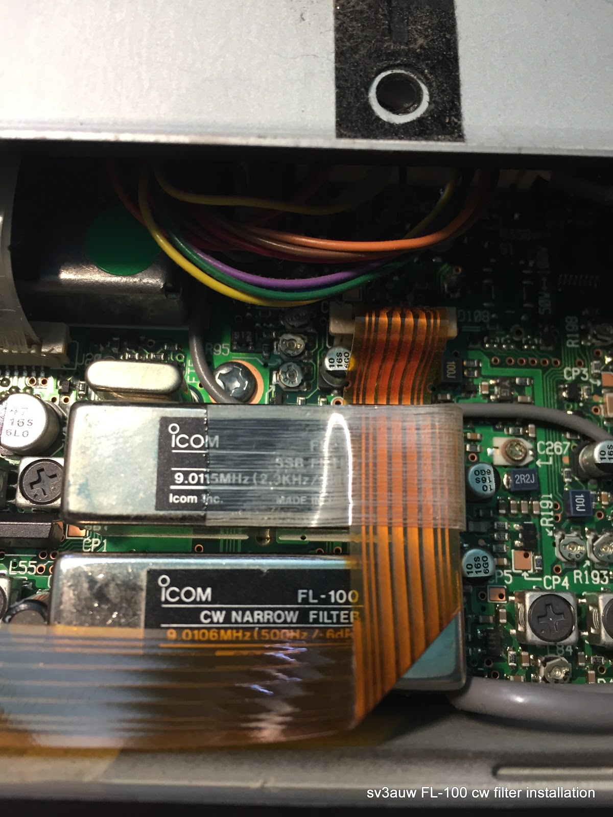
Remove the 5 screws that holds the top cover in place.


Lift carefully the cover because the speaker cable is to sort to work with.


There is only one space for filter and that is were you are going to install yours!
Lift and move aside the flex line, place the filter in position, push it downwards gently and that's it!


Press the "LOCK" button and switch on the radio pressing the "POWER" button.

It will take you to menu screen whereas you will select the 19th option and will choose the installed filter.

The FL-100 in our case.

Switch off the radio and the switch it on again. Congrats! You've done it!
Press the "NAR" button and you'll come down to 500Hz!

Enjoy!
Εγκατάσταση το φίλτρου FL-100 στο IC-706. Είναι τόσο απλή!
Ξεβιδώνετε 5 βίδες. 3 στην ευθεία πίσω από το μεγάφωνο και 2 πισω και στα πλάγια όπως βλέπετε στις φωτογραφίες.
Ανασηκώνετε προσεκτικά το καπάκι με προσοχή για να μήν κοπή το καλώδιο του μεγαφώνου. Μετακινείτε ελαφρά την καλωδιολωρίδα και εισάγετε προσεκτικά το φίλτρο. Το πιέζετε μαλακά να κουμπώσει και... κλείνετε!
Αυτό ήταν!
Εισέρχεστε στο menu πιέζοντας ταυτόχρονα το LOCK και το POWER κι επιλέγετε την επιλογή 19 όπου ορίζετε ως φίλτρο αυτό που μόλις βάλατε. Σβύνετε, ανοίγετε και το φίλτρο είναι στην θέση NAR και σας περιμένει!
Ούτε κολλητήρι, ούτε πολύμετρα ούτε τίποτα παρά ένα απλό κατσαβίδι Philips. (το λένε και στραβο-κατσάβιδο!!!)
Καλή επιτυχία!
Wednesday, 25 April 2018
...another μBITX bites the ...bench!
Other than the known glitch on CW it delivers key-down approx. 10Watts.
Same by whistling on the mike. Definitely R63 and R65 needs to change according to the BITX site.
I don't know it's sensitivity yet as I test it on a dummy load after I put it temporarily in a empty food container.
Tests will continue and I will keep you informed!
Stay warm, stay dry!
Το μBITX το αγόρασε ένας φίλος και μου το έστειλε για την αρχική συνδεσμολογία κι εύρεση προβλημάτων.
Το χειριστήριο ακούγεται να έχει πρόβλημα χρονισμού και το μικρόφωνο θέλει "στεντόρεια" φωνή για να βγάλει μερικά από τα 10watts της εξόδου.
Στην σελίδα του BITX δίνονται λύσεις τις οποίες και θα εφαρμόσω προτού το επιστρέψω.
Να ξέρετε ότι είναι ένας 10βατος ρ/ε πομποδέκτης και αξίζει τα χρήματά του μέχρι την τελευταία δεκάρα!
Μείνετε συντονισμένοι!


Friday, 30 March 2018
QCX CW kit by Country

Διάβαζα σήμερα τα στατιστικά πωλήσεων του QCX CW kit ανά Χώρα και μετά λύπης μου διαπίστωσα ότι έχουν πωληθεί 10 ή και λιγότερα τέτοια κιτ στην Ελλάδα.
Δεν κερδίζω τίποτα από τις πωλήσεις αυτού του πολύ αξιόλογου, κατά την γνώμη μου - IMHO, κιτ ούτε από διαφημίσεις της Google.
Αντίθετα πιστεύω ότι ο συνάδελφος αγοραστής του, έχει πολλά να μάθει και κατασκευάζοντας το κιτ αυτό καθαυτό αλλά και από την θεωρία η οποία το συνοδεύει στο manual. Όχι μόνο τι κολλά και που, αλλά και το ΓΙΑΤΙ!
Δεκάδες οι "τοίχοι κατασκευών" στο ΦΒ αλλά, εδώ όπου θα δικαιολογούσαν τον τίτλο τους... τίποτα.
Τελικά το CW είναι φίλτρο.
Ξεχωρίζει τους χειριστές ασυρμάτου από τους χρήστες μαύρων κουτιών.
Αν παρ' ελπίδα θελήσετε να το κατασκευάσετε η μπάντα των 40m αποδεικνύεται αυτή με την μεγαλύτερη προτίμηση μεταξύ των άλλων κατασκευαστών!

Thursday, 4 January 2018
QRP Labs QCX 5W CW Transceiver kit

Twas 'bout time to start building the kit!
I'll keep you updated.

Thursday, 16 November 2017
Poor man's tower! An almost complete presentation.

When me and my technical team design the SHT-to-SHT* retractable antenna tower, we didn't take into account some things it could make my day and my climbing better and easier!
Like, the distance my leg has to rise when going from one step to the other is 30cm whereas it could be 25 OR I could have fit steps on both sides of the tube making the climb effortless.
Especially the last two of them MUST be in pair so to have a better stand and put your whole weight on both legs. Being there it's not a bad idea to ad another pair of steps so you can climb even higher and work above rotator cage level. IF YOU DARE!!!
The base plate of the tower is 15cm by 15cm whereas it could be, lets say 20x20 or ever 25x25 centimetres. There is no safety issue as it is now, simply it gives you extra confidence of stability.
The steps were made from mild steel angle iron 2x2x15 centimetres and they were uncomfortable for my foot to stay on for prolonged time.
So what was the upgrade about?!
For start I welded one more step to pair it with last one already existed at the top of the tube and then another pair welded even higher! All these three steps were made by the same materiel but of diferent size. 4x4x15centimetres this time.
I had thought that, while standing on the top step(single legged!) I could possibly lift the whole apparatus, SHT, rotator cage and Dipole using my own strength.
I was wrong because I am not that strong and the rest is too heavy!
There I thought the winch solution. I bought a 2500 lbs manual winch, strong enough to pull small boats ashore to use it as a puller or lifter. A good friend of mine(name withheld) provided me with two special type sliding door rollers and that was almost everything I needed to have.
After I made the necessary arrangements with a crane company, my Odyssey started.
The existed tower came to ground level sweet as a treat and that was the only easy thing.
I had to take it to the workshop I had initially construct it because of better welding technics and abundance of various metal bits and pieces I was going to need.

I welded one of the two rollers at the bottom of the sliding 40x40mm SHT and the other one atop of the 60x60mm SHT. Exactly opposite I welded a single chain ring as a secure point for the steel wire I was going to use.

The theory was, by pulling and rolling the steel wire on the winch drum, the inside SHT would slide outwards. Upwards in my case!
So it was although I had to run the wire, assembly and test it all by my own and no helping hand.
In the mean time I had to make a concrete block to rise the base of the tower due the roof insulation.
Then it was the imminent rain threat. It had to rain and consequently had to dry to pour the concrete for the insulation and then I had to wait for it to dry enough to ask the crane company to brink back my updated toy!

Luckily and after an almost complete month of worries and alot of go back and forth, the tower installed as it should.
And works as it should!
In between my trials of rising and lowering the inside SHT and the taller boom, 3meters tall now rather the 1.2meters which was before, I found time to install also a 80m wire dipole barely noticed against the sky.

Some of the changes is not difficult to be seen in the photos where some others I'll take a photo of them given the opportunity.
The concept of an antenna tower and what was made off, started a couple of years earlier discussing with a friend of mine(name withheld). From all the available building materials and construction options it was accepted as a very easy, cheap and secure way to make a structure a.k.a. tower to keep one's antennas high in the sky!
Precious help was given by Sotiris SV1BDO, revealing to me the secrets of sliding steel hollow tubes. Tnx Sotiris!
A big thank you to Makis at the workshop for his expertise and the welding lessons. A big potato for his boss!
*SHT for steel hollow tube.
Θεωρούσα ότι θα μπορούσα να σηκώνω ευκαιριακά τον μέσα κοιλοδοκό του πύργου μόνο με την δύναμή μου!

Τελικά το όλο σύστημα απαρτιζόμενο από την 6μετρη κοιλοδοκό, το κλουβί του ρότορα μαζί με αυτόν και η σωλήνα ύψους 1.20 και η κεραία ήταν πολύ βαριά για να το καταφέρω. Ειδικά όταν πατούσα στο ένα πόδι σε σιδερογωνιά πλάτους 2 εκατοστών και το μόνο βολικό πιάσιμο ήταν στο ύψος των ώμων.
Γιαυτό και κάποιες άλλες βελτιώσεις οι οποίες προέκυψαν στην πορεία, χρειάστηκε να κατεβάσω τον πύργο και να τον πάω στο μηχανουργείο.
Ξέχωρα από τα σκολιανά μου που άκουσα από τον Γιάννη Αφεντικό, η δουλειά που έκανε ο Μάκης στις κολλήσεις είναι καταπληκτική και σίγουρη!

Το εύκολο ήταν να προσθέσω μερικά σκαλοπάτια ακόμα, τρία τον αριθμό στην κορυφή, το ένα για να ζευγαρώσω το τελευταίο υπάρχον και τα άλλα δύο ακόμα υψηλότερα σε σημείο που αν το αντέχω να μπορώ να ανεβαίνω πιό πάνω κι από το κλουβί του ρότορα.
Για την ανύψωση τώρα, αγόρασα ένα μαγκάνι το οποίο χρησιμοποιούν για να έλκουν τα σκάφη επάνω στο τρέϊλερ κι ένας φίλος με βόλεψε δύο ράουλα γκαραζόπορτας για να τρέχει το συρματόσκοινο επάνω τους.
Το ένα ράουλο κολλήθηκε στο κάτω μέρος της μικρής κοιλοδοκού και το άλλο την κορυφή της μεγάλης. Απέναντι από αυτό κολλήθηκε κι ένας κρίκος αλυσίδας σαν σημείο αγκίστρωσης του συρματόσκοινου. Το σκεπτικό λειτουργίας είναι, τυλίγοντας το συρματόσκοινο στο μαγκάνι και μειώνοντας έτσι το μήκος του ο 40*40 κοιλοδοκός γλιστρά μέσα στον 60*60 και ανεβαίνει προς τα επάνω. Παρ' όλες τις αμφιβολίες μου για το τελικό αποτέλεσμα λειτουργεί καταπληκτικά κι αυτό σβήνει τα μύρια όσα προβλήματα και τρεξίματα είχα μέχρι να το καταφέρω!


Το όλο εγχείρημα μου πήρε αρκετό καιρό διότι είχα να φτιάξω μιά τσιμεντένια βάση έτσι ώστε να σηκωθεί ο πύργος ψηλότερα όταν θα γύριζε από τις βελτιώσεις αλλά και γιατί ήταν στο πρόγραμμα να στρωθεί η κακής ποιότητας ταράτσα με μονωτικά Dow και νέο τσιμέντο.

Αστάθμητος παράγοντας σε όλα αυτά η βροχή η οποία αναμενόταν προς το τέλος Οκτωβρίου.
Ο Σωτήρης SV1BDO με βοήθησε με μερικές ιδέες του σχετικά με τους πτυσσόμενους πύργους του οποίους κατασκευάζει και τον ευχαριστώ κι από 'δω!
Εν ολίγοις έτσι έχουν τα πράγματα κι αυτά έκανα για να βελτιώσω το πυργοσύστημά μου. Πιστεύω ότι οι φωτογραφίες είναι κατατοπιστικές κι όσες δεν κατάφερα να βγάλω, θα το κάνω με την πρώτη ευκαιρία.

Subscribe to:
Comments (Atom)