.

Ο λόγος στασίμων 1:1 ενός κεραιοσυστήματος, δεν συνεπάγεται τον 1:1 λόγο μεταφοράς ισχύος, προς την κεραία!
Showing posts with label hf antenna. Show all posts

Wednesday, 20 April 2022

OPINIONS SOUGHT ON DOUBLE BAZOOKA ANTENNA:

Ερώτηση για την απόδοση της  Double Bazooka.
Απάντηση με κακά μαντάτα.

...I am researching the Double Bazooka as another antenna I would like to experiment with on 20/40 meters. I'd like to hear from anyone who has used this antenna in the past.....is it more than just a glorified dipole or inverted V ? Has anyone tried building it with 75 ohm coax (I have quite a bit of this left over from my cable TV days).
If It somehow achieves performance that can not be realized with an ordinary Inverted V, I may give it a shot.
Thank You. Rod, K5FRH...

Charles Tom Rauch
This antenna has been analyzed and tested many times over my radio lifetime.
I once owned Midport Electronics and one of my employees sold them at Hamfests using unrealistic claims. I had BC field strength meters, because I did some SW and AM station antenna proofs.
I took one to my house and set it up in the clear and made all sorts of measurements. (I can't recall if it was actually one of his, or one I made. That was like around 1970 or so.)
It was ever so slightly lossier than a dipole, no quieter for noise, and actually not any noticeable amount wider BW than a regular old dipole made from the same materials. He continued to justify selling them, saying "people report they are better so I'll keep selling them" or something like that.
I tested another on for someone from IAC years later. It measured exactly the same as earlier tests, within instrument and site tolerances.
Walter Maxwell in "Reflections" does a pretty good analysis, as has other over the years. His theoretical conclusions paralleled the measurements I made some years earlier (around 1970 or so).

https://www.facebook.com/groups/antennabuilding/permalink/3479615402272284

Monday, 25 September 2017

Ατσαλόσυρμα σε Βραχέο δίπολο. Μπορεί να χρησιμοποιηθεί?

Σχετική εικόνα
Σε τακτικά διαστήματα σε Ελληνικά αλλά και διεθνή Fora, τίθεται το ερώτημα:
"Μπορεί να χρησιμοποιηθεί ατσαλόσυρμα για κατασκευή δίπολης κεραίας"?

Το ερώτημα τέθηκε πάλι μερικές μέρες πριν στο forum RSBG όπου ανάμεσα στα, ναι-όχι-ίσως-μπορεί-δεν χάθηκε ο κόσμος-υπό προϋποθέσεις, κάποιος έδωσε ένα link Αυστραλιανού Συλλόγου ο οποίος δημοσίευσε ένα άρθρο το οποίο έγραφε και τεκμηρίωνε όλα αυτά τα οποία εσείς διαβάζετε σε αυτό το ιστολόγιο από τον Φεβρουάριο του 2009!
Έγραφε λοιπόν στο εν κατακλείδι ο Tim VK2BT: ...I would NOT recommend using stainless wire for a “low impedance” antenna (such as a simple dipole). I learned this lesson the hard way myself when I recently constructed one for myself at home, and found that I could NOT match it properly. (δεν θα συνιστούσα την χρησιμοποίηση του ατσαλοσύρματος για κεραία Χαμηλή Σύνθετης Αντίστασης π.χ. ως ένα δίπολο. Πήρα το μάθημά μου με άσχημο τρόπο όταν το είχα κατασκευάσει στο σπίτι και ΔΕΝ μπορούσα να το συντονίσω.)
Το όλο άρθρο είναι στην σελίδα του Manly-Warringah
Radio Society MWRS και διαβάζεται εδώ καθώς και το pdf με την eznec ανάλυση το οποίο θα διαβάσετε εδώ.

Επαναθέτοντας λοιπόν το ερώτημα:"Μπορεί να χρησιμοποιηθεί ατσαλόσυρμα για κατασκευή δίπολης κεραίας"?
Η απάντηση είναι μονολεκτικά ΟΧΙ!
ΟΧΙ ως κεραία αλλά ως στήριγμα της πραγματικής κεραίας, πραγματικά μπορεί και είναι ΝΑΙ!
Tip. Μου ζήτησε ένας συνάδελφος να αγοράσει αρκετά μέτρα από το multistranded του οποίου έχω μερικές καρούλες και πωλώ. απαραίτητη προϋπόθεση ήταν να αντέχει τα 12 Μποφόρ των μελτεμιών του Αιγαίου. Του έστειλα μερικά μέτρα σύρμα για δοκιμή η οποία με την σειρά της απέδειξε ότι το 7stranded σύρμα έχει την απαραίτητη αντοχή στην μόνιμη έλξη αλλά όχι στα τινάγματα και τις ριπές του αέρα. Επάνω στην κουβέντα για προτεινόμενες λύσεις πρότεινα το εξής. 
Να συνεχίσει να υπάρχει το ατσάλινο δίπολο, ΜΟΝΟ ΩΣ ΣΤΗΡΙΓΜΑ του χάλκινου αγωγού ο οποίος θα τρέχει παράλληλα. Τα "επιδερμικά φαινόμενα" τρέχουν στην επιδερμίδα του αγωγού διαλέγοντας πάντα την καλύτερη αγωγιμότητα άρα στο συγκεκριμένο παράδειγμα, η RF θα επιλέγει πάντα να τρέχει στον Χαλκό αδιαφορώντας για το Ατσάλι δίπλα του.
ΝΑΙ! Μπορείτε να χρησιμοποιήσετε ατσαλόσυρμα ως στήριγμα του χαλκοσύρματος της δίπολης ή άλλης κεραίας και τίποτε άλλο! Απλά μην το πληρώνετε ώς "σπέσιαλ"!

Wednesday, 18 January 2017

Controversies!

the ANTENNA

the STATION

the LOCATION

a station is as good as it's antenna (and the surroundings!)

Στην γούβα κι αυτός. Κρίμα!


Wednesday, 3 February 2016

the Best HF Antennas (so far!)


Before I start advise others on good and better antennas it's time to show you what kind of antennas I use at this moment.
First I would like to remind you once again, that there is no Magic or Ideal antenna.
The "best antenna", is the antenna that one can install given the space, time, and money.
My antennas!
I have a 28-meter end-fed wire installed in inverted L shape. The vertical part is 8 meters and the horizontal one, 20 meters.

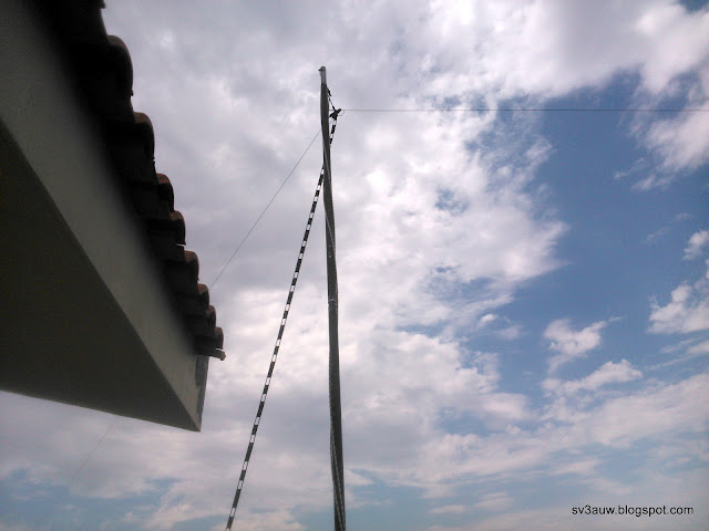
I also have the Create 730V multi-band dipole which is no longer fed with coaxial cable, RG213 type, but with ladder-line.The ladder-line ends at a current balun just under the roof and from there I use 1.2 meters of RG58 coaxial cable to connect the manual ATU!

The reason I changed the feeding is twofold. First when poor old Collins 30L1 decides(!) to operate, something change either in balun itself or in the antenna traps.
Second, I have a lot of SWR which is not necessarily a bad thing except when they have to cross the lossy coaxial cable. There, there are large power losses in transmission and reception. In contrast the use of ladder-line overcomes the problem and allows an excellent transmission with a minimum of losses!
Your question now is, what antenna is better?
Define "best"!
Both have their positives and negatives. What largely satisfy me is that one complements the other.
3.690MHz
The dipole is performing so badly, so the wire is my only option. Good performance in a radius of 1000miles
7.140MHz
The wire in the majority of cases works very well on a inter-SV level, and when propagation begins to open, dipole takes the edge on distant stations.
10.100MHz
Same as 40m. The dipole is marginally better.
14.250MHz
Surprisingly wire antenna receives well plenty of stations which I can work. So does the dipole, with a small advantage. Listening, is somewhat better.At the opening of the band, the two antennas can be side by side in performance. When the band is fully open the dipole in the majority of cases is up to two S-units or 12db, better!
18.140MHz
Although on the transceiver side I see 1: 1 SWR and zero returned power, the dipole is not working properly. I can feel the lack of liveliness of the Receiver and the reception of more stations with the wire antenna. 80% ~ 20% in favour of the wire antenna.
21.250MHz
Here, as in 20m band, dipole dominates in most cases, of the wire. This doesn't stop me do 4S7 or VU2 with it!
24.950MHz
Here again, my dipole sounds "deaf". Using the wire antenna, propagation and luck, I managed work an S79.. station.
28.450MHz
I usually see in the Log4OM several dx stations spotted but my contacts are so few or so random, that I have not settled on stats.
Recapping.
It is worth noting that in many cases the end-fed shows a better reception than the dipole but I prefer to hear clearly the station with S8 and a noise level of S4 than a station mixed with QRM and noise together at S9!
The dipole is at a height of only 4 meters above the ground in the direction East - West or 80 / 260. The wire antenna has almost the same direction located 4 meters south of Dipole and 4 meters higher than that. Nevertheless the dipole having a "V" shape pointing and sounds to be more DX-potential.
What comes next?
I intend to lift the base of the dipole to 6 meters height, I have already purchased and paint a hollow beam 40x40x600, and I will also rise the end of the horizontal leg of the L, by 5m (+ 3m considering the height of the next building!).
I think it will improve the reception of  distant stations, alas reducing somewhat, the performance of the end-fed in 40m and 80m rag-chews with Greek colleagues.

Given that this is the best I can do with my antennas, they are the BEST ANTENNAS !!!


Προτού αρχίσω να συμβουλεύω άλλους για κεραίες καλό είναι να σας πω και να σας δείξω τι είδους κεραίες χρησιμοποιώ αυτή την στιγμή.
Κατ' αρχάς, θα ήθελα να σας πω άλλη μία φορά ό,τι δεν υπάρχει η Μαγική ή Ιδανική κεραία.
Η καλύτερη κεραία είναι η κεραία την οποία μπορεί κάποιος να εγκαταστήσει, δεδομένου του χώρου, του χρόνου και των χρημάτων τα οποία διαθέτει.
Λοιπόν τα δικά μου τώρα!
Έχω ένα σύρμα μήκους 28 μέτρων εγκατεστημένο σε σχήμα Γ. Το κάθετο σκέλος είναι 8 μέτρα και το οριζόντιο 20 μέτρα.
Έχω επίσης και την Create 730V την οποία δεν την τροφοδοτώ πλέον με ομοαξονικό καλώδιο, RG213, αλλά με 5 μέτρα ανοικτής γραμμής. Γραμμή η οποία καταλήγει σ' ένα current balun ακριβώς κάτω από την στέγη κι από εκεί με 1,2 μέτρα RG58 ομοαξονικό καλώδιο γίνεται η σύνδεση στο συντονιστικό!
Ο λόγος για τον οποίο της άλλαξα την τροφοδοσία είναι διπλός. Κατ' αρχάς όταν αποφάσιζε ο ταλαίπωρος Collins να λειτουργήσει, κάτι άλλαζε είτε στο balun αυτό καθαυτό ή στα traps της κεραίας.
Είχα πολλά στάσιμα τα οποία δεν είναι απαραίτητα κάτι κακό παρά μόνο, όταν έχουν να διαβούν την κλεισούρα ενός ομοαξονικού καλωδίου. Εκεί υπάρχουν μεγάλες απώλειες ισχύος στην εκπομπή και στην λήψη. Αντίθετα στην απεραντοσύνη της ανοικτής γραμμής δεν έχουν κανένα πρόβλημα κι εκπέμπονται όταν έρχεται η σειρά τους παρουσιάζοντας ελάχιστες απώλειες!

Το ερώτημα σας τώρα είναι, ποιά κεραία είναι η καλύτερη;
Ορίστε μου το “καλύτερη”!
Και οι δύο έχουν τα θετικά τους αλλά και τα αρνητικά τους. Αυτό που με ικανοποιεί σε μεγάλο βαθμό είναι ότι η μία συμπληρώνει την άλλη.
3.690MHz
Το δίπολο δεν αποδίδει τόσο χαμηλά κι έτσι το σύρμα είναι η μόνη μου επιλογή. Καλή απόδοση σε Ελληνικό-Ευρωπαϊκό επίπεδο.
7.140MHz
Το σύρμα στην πλειοψηφία των περιπτώσεων ακούει πολύ καλά σε πανελλαδικό επίπεδο εκεί που όταν αρχίζει ν' ανοίγει η διάδοση το δίπολο παίρνει την προτίμηση των μακρινών σταθμών.
10.100MHz
Το ίδιο με τα 40m. Οριακά καλύτερο το δίπολο.
14.250MHz
Παραδόξως το σύρμα ακούει αρκετά καλά σταθμούς τους οποίους μπορώ να δουλέψω. Το ίδιο και το δίπολο με ένα πολύ μικρό πλεονέκτημα. Ακούω, κάπως καλύτερα, σταθμούς που δεν μπορώ να δουλέψω! Μέχρι να ανοίξει πλήρως η μπάντα, οι δύο κεραίες μπορεί να είναι δίπλα-δίπλα σε απόδοση. Όταν ανοίγουν τα 14άρια το δίπολο στην πλειοψηφία των περιπτώσεων είναι έως και δύο μονάδες ή 12db, καλύτερο!
18.140MHz
Μολονότι προς την πλευρά του π/δ, βλέπω 1:1 λόγο στασίμων και μηδενική επιστρεφόμενη ισχύ, το δίπολο δεν δουλεύει σωστά. Το νιώθω από την έλλειψη ζωντάνιας του Δέκτη αλλά και από την λήψη περισσότερων σταθμών με την συρματοκεραία. 80%~20% υπέρ του σύρματος.
21.250MHz
Εδώ όπως και στα 20m το δίπολο κυριαρχεί στις περισσότερες των περιπτώσεων, από το σύρμα. Αυτό βέβαια δεν με εμπόδισε να κάνω 4S7 ή VU2 με αυτό!
24950MHz
Πάλι εδώ το δίπολο μου ακούγεται “κουφό”. Με την συρματοκεραία, διάδοση αλλά και τύχη, έκανα S79.
28.450MHz
Εδώ βλέπω στο Log4OM διάφορους μακρινούς σταθμούς σποταρισμένους αλλά οι επαφές μου είναι τόσο λίγες ή τόσο τυχαίες που δεν έχω κατασταλάξει στατιστικά.
Ανακεφαλαιώνοντας.
Αξίζει να σημειωθεί ότι σε πολλές περιπτώσεις το σύρμα δείχνει ν' ακούει καλύτερα από το δίπολο αλλά προτιμώ να ακούω καθαρά το σταθμό με σήμα 8 κι επίπεδο θορύβου 4 παρά σήμα και θόρυβο αχταρμά στις 9 μονάδες!
Το δίπολο είναι σε ύψος μόλις 4 μέτρων από το έδαφος με κατεύθυνση Ανατολή – Δύση ή 800 / 2600. Η συρματοκεραία έχει σχεδόν την ίδια κατεύθυνση ευρισκόμενη 4 μέτρα Νοτιότερα του Διπόλου και 4 μέτρα υψηλότερα από αυτό. Παρόλα αυτά το δίπολο το οποίο έχει σχήμα “Vδείχνει και ακούγεται να είναι περισσότερο DX-ικό.
Τι μέλει γενέσθαι;
Έχω σκοπό να σηκώσω την βάση του διπόλου στα 6 μέτρα, έχω ήδη αγοράσει και βάψει έναν κοιλοδοκό 40Χ40Χ600, κι επίσης να ψηλώσω το τελείωμα του οριζόντιου σκέλους του Γάμμα στα 5μέτρα (+ 3μέτρα ο όροφος των δίπλα!).
Πιστεύω ότι θα βελτιώσω τις αποδώσεις των στους μακρινούς σταθμούς, μειώνοντας κατά τι, την απόδοση της συρματοκεραίας στα 40m και 80m σε συνομιλίες με Έλληνες συναδέλφους.
Εφόσον είναι ότι καλύτερο μπορώ να κάνω από κεραίες, είναι οι ΚΑΛΥΤΕΡΕΣ ΚΕΡΑΙΕΣ!!!


Friday, 14 August 2015

Multiband Dipole Antenna.


I installed a dipole with a side length of 22 meters at SV1AIA. The aim was to cover the whole HF range ie from 160m up to 10m. with only one antenna. RF is fed to the center of the dipole via 4 meters of ladder line and is tuned with the help of a Furuno AT-5075 ATU you see at the base of the mast.

Two lengths of wire in the form of dipole, can tuned over a wide frequency range, if we manage to adapt the specific impedance of the feed line to the Impedance (Z) of the dipole at the frequency that we have selected for transmission.
In most of the time there will be mismatches and high standing wave ratio. This has almost no importance because in most cases, if the feed line is Ladder Line, the  power losses due to standing waves(SWR) are minimal. Also the transceiver sees Impedance 50 Ohms at the input of ATU and delivers maximum power while the ATU being almost in the center of the dipole assuming the role of Gama match, T match, Hairpin match etc! Small mismatches because of the length and Z, of the ladder line are minor and the final result is not affected .
This is a true multi-band antenna with emission of more than 98 % of the power that reaches the connector input of ATU overcoming the losses of the coaxial cable. To all those who have automatic ATU's, I would highly recommend them to construct this antenna. The ease of matching / tuning and performance will amaze you !

As you can see in the accompanying pictures, at the first stage of the installation , I used a pulley mounted straight on the mast. This resulted the proximity of the ladder line with the grounded metal mast. Kostas made ​​a bracket length of half a meter zeroing the proximity losses of ladder line due the metal mast.


Εγκατέστησα ένα δίπολο με μήκος πλευράς 22 μέτρα στον SV1AIA. Σκοπός ήταν να καλύπτει όλο το HF φάσμα, ήτοι από τα 160 μέτρα έως και τα 10 μέτρα.
Η τροφοδοσία γίνεται στο κέντρο του διπόλου με 4 μέτρα ανοικτής γραμμής και ο συντονισμός με το  AT-5075 ATU της Furuno που βλέπετε στην βάση του ιστού. Δύο μήκη σύρματος με την μορφή διπόλου, μπορούν να συντονίσουν σε ένα μεγάλο εύρος συχνοτήτων, εφόσον καταφέρνουμε να προσαρμόσουμε τη συγκεκριμένη Σύνθετη Αντίσταση (Z) της γραμμής τροφοδοσίας με την εκάστοτε Σύνθετη Αντίσταση του διπόλου στην συχνότητα που έχουμε επιλέξει για εκπομπή. Σε αρκετές περιπτώσεις θα υπάρξει δυσπροσαρμογή και υψηλός λόγος Στασίμων Κυμάτων. Αυτό δεν έχει σχεδόν καμία σημασία διότι στην πλειοψηφία των περιπτώσεων, εφόσον η γραμμή τροφοδοσίας είναι ανοικτή γραμμή, οι απώλειες ισχύος λόγω Στασίμων Κυμάτων είναι ελάχιστες. Επίσης ο πομποδέκτης βλέπει Σύνθετη Αντίσταση 50 Ω και αποδίδει το μέγιστο της ισχύος του ενώ το ATU στο κέντρο σχεδόν του διπόλου αναλαμβάνει τον ρόλο του Gama match, T match, Hairpin match etc! Η μικρή δυσπροσαρμογή λόγω του μήκους της ανοικτής γραμμής είναι ήσσονος σημασίας και δεν επηρεάζει το τελικό αποτέλεσμα.
Αυτή είναι  μιά  πραγματική πολυζωνική κεραία με εκπομπή πάνω του 98% της ισχύος ή οποία φτάνει στον κονέκτορα εισόδου του ATU ξεπερνώντας τις απώλειες του ομοαξονικού καλωδίου. Σε όλους όσους έχουν αυτόματα ATU's θα τους συνιστούσα ανεπιφύλακτα να κατασκευάσουν αυτήν την κεραία. Η ευκολία συντονισμού/προσαρμογής και η απόδοση της, θα σας καταπλήξουν!

Όπως μπορείτε να δείτε στις συνημμένες φωτογραφίες, στο πρώτο στάδιο της εγκατάστασης, χρησιμοποιούσα ένα ράουλο στερεωμένο επάνω στον ιστό. Αυτό είχε σαν αποτέλεσμα την γειτνίαση της ανοικτής γραμμής με το μέταλλο του γειωμένου ιστού. ο Κώστας έφτιαξε ένα μπρακέτο μήκους μισού μέτρου απομακρύνοντας έτσι την ανοικτή γραμμή από τον μεταλλικό ιστό.


Some time ago a fellow radio amateur asked me about the number and the length of counterpoise wire(s) for his random wire antenna of 27.5 meter exactly!
My answer and suggestion to him was to run another length of 27.5 meter opposite to the direction of the one already installed. Thus creating a dipole antenna more like an Inverted Vee. For DX sake I hope that he followed my advise. If not, he better start doing it!


Πριν από λίγο καιρό ένας συνάδελφος ραδιοερασιτέχνης με ρώτησε για τον αριθμό και το μήκος των αντίβαρων για μιά τυχαίου μήκους, 27.5 μέτρων, συρμάτινη κεραία.
Η απάντηση και πρότασή μου ήταν, να τρέξει ένα άλλο μήκος σύρματος 27.5 μέτρων αντίθετα προς την κατεύθυνση του ενός ήδη εγκαταστημένου. Δημιουργώντας έτσι ένα δίπολο, κάτι σαν ένα ανεστραμμένο Vee. Για DXικό καλό του, ελπίζω ότι ακολούθησε τις συμβουλές μου . Αν όχι, καλύτερα να αρχίσει να τεντώνει σύρματα!!!

Tuesday, 24 March 2015

G5RV HF antenna. Μύθος ή πραγματικότητα? updated


Όσοι δεν έχετε κατασκευάσει την G5RV ακόμα, καλά έχετε κάνει. Όσο για εσάς που την έχετε, καλά θα κάνατε να σκέπτεστε την αναβάθμιση της.
Η κεραία ονομάστηκε G5RV προς τιμή του σχεδιαστή της Lewis Varney (g5rv). Δεν είναι τίποτα άλλο από ένα συμμετρικό δίπολο και ένα ορισμένο μήκος ανοικτής γραμμής σαν κάθοδο.
Το πλεονέκτημα αυτής της συνδεσμολογίας είναι το γεγονός του ότι μπορούμε να δουλέψουμε τα 20 Μέτρα χωρίς Μονάδα Προσαρμογής Κεραίας / Antenna Tunning Unit (ATU)ή και Τιούνερ στην καθομιλουμένη!
Ναι αλλά! 
Αυτά συνέβαιναν τότε, στα τέλη της δεκαετίας του 50 με αρχές της δεκαετίας του 60, όπου όλα τα μηχανήματα είχαν το γνωστό κύκλωμα Π στην έξοδό τους και κατάφερναν να διορθώνουν μόνα τους μικρές αποκλείσεις στην Σύνθετη Αντίσταση που έβλεπαν.
Η αρχική G5RV μετά την ανοικτή γραμμή δεν χρησιμοποιούσε ομοαξονικό καλώδιο αλλά πλακέ 72 Ωμ. Η αντίσταση τερματισμού της ανοικτής γραμμής είχε υπολογισθεί από τον κατασκευαστή ότι ήταν 90 Ωμ οπότε ο λόγος στασίμων στην ένωση ήταν 90/72 = 1.25:1!
Τα σημερινά μηχανήματα έχουν έξοδο 50 Ωμ, άρα θα έχουμε λόγο στασίμων 90/50 = 1.8:1!
Μόνο για τα 20 Μέτρα, διότι από εκεί και μετά, στις άλλες συχνότητες, η χρήση Τιούνερ είναι επιβεβλημένη!
Πηγαίνετε τώρα πίσω από μερικά τεύχη των Ραδιοτηλεπικοινωνιών και θυμηθείτε τι σας έλεγα για τα στάσιμα και τις απώλειες των ομοαξονικών καλωδίων.
Επειδή έχουν περάσει πολλά χρόνια από τότε, ακόμα πιό εύκολα ακολουθήστε το λινκ και διαβάστε το στο Scribd. Εκεί θα βρείτε αρκετές πληροφορίες τεχνικού-ραδιοερασιτεχνικού ενδιαφέροντος οι οποίες θα εμπλουτίζονται με την πάροδο του χρόνου!
Σε λόγο στασίμων 1.1:1 έχουν τις λιγότερες επιτρεπόμενες απώλειες. Όταν όμως ο λόγος στασίμων μεταβάλετε οι απώλειες ανεβαίνουν κατακόρυφα.
Αντιγράφω έναν πίνακα από το RadCom Φεβρουάριος 2006 και από άρθρο του Peter Dodd G3LDO.
Band                 R ± J,                        RG213                   RG58 
MHz              tuned line end          SWRs      Loss db     SWRs      Loss db 
3.6                   25 ± 260                64/47       3.1          64/21        3.4 
7.0                   202 ±444               24/14       2.3          24/10.8     3.7 
10.1                 337 ± 966              65/19        5.2          65/13       6.2 
14.2                 104 ± 4                 2.1/1.9      0.6          2.1/1.8     0.8 
18.1                 322 ± 706              37/12.8     4.8          37/9.5      5.8
21.2                 235 ± 684              44/12.8     4.8          44/9.3      6.9
25.0                 177 ± 131              5.5/4.2      1.4          5.5/3.7    1.9
28.5                 1233 ± 1215          49/11.6      6.1          49/11.6    7.6
R+_J. Αντίσταση και ανάδραση στο τέλος της ανοικτής γραμμής της G5RV.
SWRs. Λόγος στασίμων κυμάτων στις δύο άκρες του ομοαξονικού καλωδίου.(τιούνερ και ανοιχτή γραμμή)
Loss db. Λόγος απωλειών λόγω της δυσπροσαρμογής.

Όπως μπορείτε να δείτε σε όλες τις ερασιτεχνικές περιοχές, ο λόγος στασίμων και από τις δύο μεριές του RG 213 είναι μεγάλος και κατά προέκταση μεγάλες είναι και οι απώλειες. Δεν γίνετε σκέψη για RG 58 διότι οι απώλειες είναι τουλάχιστον 1/3 μεγαλύτερες!
Αντίθετα η ανοικτή γραμμή δεν δείχνει να επηρεάζεται ιδιαίτερα και μολονότι έχει και αυτή υψηλό λόγο στασίμων και από τις δύο άκρες της η απώλειες που αναπτύσσονται είναι ελάχιστες!
Οι υπολογισμοί της ανοικτής γραμμής έχουν γίνει με λίγο μικρότερο μήκος κεραίας. Η διαφορά με την G5RV δεν είναι υπολογίσιμη και σίγουρα είναι προς το καλύτερο!
Γιατί να κάνετε λοιπόν την ζωή σας δύσκολη, μετατρέποντας την Ηλεκτρομαγνητική ενέργεια σε Θερμική, και να μην χρησιμοποιήσετε ανοικτή γραμμή μέχρι τον σταθμό σας?
Σίγουρα κάποιο εξωτερικό Τιούνερ θα υπάρχει! Συνδέετε την ανοικτή γραμμή επάνω σε αυτό και έχετε τις λιγότερες δυνατόν απώλειες από το κεραιοσύστημά σας!
Στην περίπτωση όπου δεν έχετε εξωτερικό τιούνερ, ή οποία είναι και η καλύτερη λύση, μπορείτε να χρησιμοποιήσετε αυτό του μηχανήματος με όχι και τόσο βέβαια αποτελέσματα από πλευράς προσαρμογής λόγο του περιορισμένου εύρους του. Όσο για την ανοικτή γραμμή και τον τρόπο σύνδεσής της είναι πολύ απλός. Τερματίζουμε την ανοικτή γραμμή σε ένα BalUn 4:1 , στην μεριά του 4 βέβαια, και το συνδέουμε με τον σταθμό με το μικρότερο μήκος ομοαξονικού καλωδίου. Για μήκος έως και 2 μέτρα μπορούμε να χρησιμοποιήσουμε ακόμα και RG 58!
Οι Άγγλοι αυτόν τον τρόπο συνδεσμολογίας τον ονομάζουν Comudipole, ο δε Doug De Maw W1FB μολονότι το προτείνει και αυτός στις πλείστες όσες κατασκευές κεραιών του, δεν του δίνει κανένα όνομα παρά μόνο το προτείνει!
Αυτά λένε οι μεγάλοι του χόμπι μας, αυτά σας μεταφέρω. Τώρα θα μου φέρει κάποιος τον αντίλογο λέγοντας ότι χρησιμοποιεί G5RV την οποία βέβαια την συντονίζει με εξωτερικό τιούνερ και έχει καταφέρει κάποια καλά DX με αυτή.
Ουδεμία αντίρρηση! Ο Les Moxon G6XN γράφει στο βιβλίο του ότι κατάφερε QSO με Αυστραλία με ισχύ λιγότερη του 1 Βαττ εκμεταλλευόμενος την γωνία ακτινοβολίας των κεραιών του παρά το κέρδος τους!
Άρα γιατί να μην δουλέψει και η G5RV και να μην κάνει και DX βέβαια?
Αυτό που σας προτείνω και σας παροτρύνω να κάνετε, είναι να εκμεταλλευτείτε στο έπακρο αυτό το κομμάτι σύρμα που έχετε κρεμάσει εκεί ψηλά και ενδεχομένως έχετε τσακωθεί με την μισή γειτονιά για να το κρατήσετε στην θέση του!
Στην περίπτωση ακόμα που δεν έχετε φτιάξει αυτήν την κεραία αλλά είναι στα πολύ κοντινά σας σχέδια έχω άλλη μία πρόταση να σας κάνω.
Δεν χρειάζεται να την κάνετε αυστηρά με τις διαστάσεις του κατασκευαστή! Μεγαλώστε τα σκέλη όσο είναι δυνατόν, αρκεί να είναι συμμετρικά. Να έχουν δηλαδή το ίδιο μήκος και από τις δύο πλευρές!
Το κέρδος σας θα είναι μεγάλο στην μπάντα των 80 Μέτρων. 20 μέτρα ανά πλευρά είναι μια πάρα πολύ ωραία κεραία για να δουλέψει με συνδεσμολογία Ταυ στα 160 Μέτρα και από εκεί και πάνω σαν δίπολο και μάλιστα με κέρδος όσο τα Μέτρα γίνονται λιγότερα!
Ήδη υπάρχει ανάρτηση με την περιγραφή αυτής της κεραίας! "Μαθήματα κεραίας από παλαιούς!"
Δεν χρειάζεται να σας το γράψω ότι τα σχόλια σε αυτή την ανάρτηση αλλά και σε όλες τις άλλες είναι ανοικτά και περιμένουν τις παρατηρήσεις σας ή και τις διαφωνίες σας

Update.
O Peter Dodd δηλώνει κατηγορηματικά: "The ATU is connected to the BalUn with a short lenght of coax cable as shown in Fig.1"
Το ίδιο που μπορείτε να διαβάσετε στο διάγραμμα της δεύτερης σελίδας στο συνημμένο pdf
Ακούω από διάφορους, ότι υπάρχει μεγάλο παίδεμα στις παράνομες μπάντες στην προσπάθεια να τιθασεύσουν την G5RV. Βρε παιδιά, εδώ υπάρχει μιά σχετική δυσκολία σχετικά με αυτήν την κεραία ακόμα και στις μπάντες για τις οποίες είναι "υπολογισμένη". Περιμένετε να το κάνετε εσείς κόβοντας δύο-δύο τους πόντους του σύρματος?!
Διαβάστε το άρθρο από το τεύχος του RadCom Ιανουάριος 2006.


Sunday, 22 March 2015

G5RV Multi-band HF Antenna

Theory of the G5RV antenna and practical installation in a small garden. MMANA predictions of the performance of the antenna installed in U shape.


I totally disagree with the construction technique of the Coiled Coaxial BalUn you can see in the photo. It has to constructed in-line and one loop after the other so the first loop will be separated from the last by 7 loops with ALL the XL contributed between them.

Περιγραφή της G5RV κεραίας και η πρακτική εγκατάστασή της σ' έναν μικρό κήπο. Διαφωνώ με τον τρόπο κατασκευής του ομοαξονικού πηνίου. Σε αυτές τις περιπτώσεις το RG δεν το μαζεύουμε σαν τριχιά αλλά το τυλήγουμε με την μία σπείρα δίπλα στην άλλη έτσι ώστε η πρώτη ν' απέχει από την τελευταία όλο τον αριθμό των σπειρών και η XL αυτεπαγωγή να είναι ή μέγιστη. Επίσης το μήκος του ομοαξονικού καλωδίου ζητά να είναι το ελάχιστο. Χμ!

Thursday, 19 March 2015

Antenna Lessons from the Old Timers!

Antenna Lessons from the Old Timers

Don Keith (N4KC) on May 24, 2007
View comments about this article! 


Lessons From the Old Timers
By Don Keith N4KC (www.donkeith.com)
Down here in Alabama, we know that three things inevitably lead to fistfights:

  • Where your loyalty lies when it comes to Alabama or Auburn football

  • Which rib joint has the best barbecue

  • And which route offers the quickest trip to the beach
On the ham bands and in Internet forums, there are at least three equally incendiary topics:

  • Contesters “crowding the bands”

  • The FCC dropping the Morse code requirement for new licensees

  • And whether an antenna cut to resonance radiates better than one that is not
Don't think these are hot topics? Then you have not been listening or reading! I'll leave the first two alone for now so I can foolishly—and at risk of “flaming,” personal attacks, and questions about my heritage—take on the third topic. I do such a silly thing primarily for three reasons:

  • We are enjoying an influx of newly licensed and newly privileged HF operators who might be able to benefit from a rational discussion on the subject.

  • We now have TEN amateur radio HF bands, and extended Advanced/Extra SSB privileges that challenge the bandwidth of most antenna system installations, especially on 80/75.

  • And as a student of history, I maintain that we can learn valuable lessons from those who came before us. The old timers who pioneered radio were correct on lots of things…including getting the most from limited antenna systems.
Here's the contention of many otherwise knowledgeable hams: you are always better off using an antenna that is cut to resonance for a particular operating frequency. That claim, many say, should be engraved in stone. It's one of the great truisms.
“Resonance.” It sounds like such a nice word. “We're in resonance on that issue, my friend.” “That topic resonates with the people!” Dictionary.com defines the word thusly: “To reinforce oscillations because the natural frequency of the device is the same as the frequency of the source.” Who could possibly argue with such a wonderful purpose? Don't all we hams want to reinforce oscillations? I know I do!
To cut to the chase, when talking about antenna systems, we call them “resonant” when the capacitive reactance present in the system is equal to the inductive reactance, and the two cancel each other out, leaving the impedance at the load point at its design value—typically 50 ohms. In that magic alignment by the gods of RF, the antenna is able to radiate into space most of the radio frequency energy that is sent to it from the transmitter via a feed line. Everything seems predestined to work well together. A dipole antenna hanging high between two trees will—on its design frequency and if properly constructed—present something close to 50 ohms impedance. Our typical coaxial feed line has a characteristic impedance of 50 ohms. The output circuit of your YaeKenEleIcomTech radio craves a 50-ohm load.
There we are! Resonance! Maximum transfer of energy occurs! Music swells, flags unfurl, the sun breaks through the clouds, and all is right with the world! We have achieved resonance!
But then, relatively new ham radio operator, you simply cannot leave well enough alone. You go and do something dumb, like touch the tuning knob and change frequency up or down the band in search of new people with whom to chat, or you go off down the band looking to chase some rare morsel of DX. Or, in a truly desperate move to find someone to talk with or to seek better propagation, you flip the switch to change to another amateur band entirely. Suddenly, your fancy, new transceiver is faced with an impedance value that is considerably removed from the Holy Grail of 50 ohms. The value may climb into the hundreds or even thousands of ohms, or drop to almost nothing, becoming disgustingly capacitive or inductively reactive. Suddenly, standing waves are introduced into the system as the RF energy encounters the ugliness of non-resonance. Energy is rudely deflected back down the coaxial feed line, all the way to the output of the transmitter from whence it came only a fraction of a second before, but it does not like the 50 ohms it finds there either. Zoom! Off it bounces once more, back up the cable, waving at its friends who are on their way back down already. But there are fewer and fewer of the reflected radio frequency waves now because some of them are being burned up—zapped energy—due to the loss in the coax.
Thankfully, if the carnage is too much—the standing waves too large a portion of the originally emitted energy—the transmitter does the only humane thing it can do. It shuts down. Then it refuses to operate at that wavelength ever again. You, dear operator, have no other choice. You return to the vicinity of the spot on the dial for which you originally designed that antenna, ignoring the limitless other frequencies and bands where others seem to play at will with no concern for the impedance encountered by their shiny YaeKenEleIcomTech radios.
But how do they do it? Gosh, there are ten amateur HF bands, and some of them are remarkably broad. Your transmitter only seems to like certain spots on those bands—those that are odd multiples of the design frequency of your nice dipole antenna, but those are few and far between and are mostly dead all the time. Finally, you ask another ham when he wanders down to where you are stuck, in the middle of the band. He is on the air, operating all over the spectrum, even though his signal is not really all that strong when compared to some of the others. Still, he seems able to move and transmit even when he is farther away than a few kilohertz in either direction, so you swallow your pride and ask him how he does it. Somehow, you manage to pull his answer out of the static and noise.
An antenna tuner! Well, of course! All you need is that wonderful device that allows you to show your expensive radio a nice 50-ohm match and all is right with the world. You can dash and flip all over the RF spectrum, working everything you hear. You had no idea the answer was so simple! Soon the box arrives from the manufacturer and you hook the “tuner” up between the rig and the coax feed line. You follow the directions and soon, after some spitting and sparking somewhere inside the radio as you learn to adjust the capacitor and inductor inside the shiny, new box, it shows you a wonderful thing on its sexy front-panel meter—a near one-to-one SWR! The rig's happy again. You go off to the hinterlands of each band, trying the thing out. It still balks in some places, but for the most part, it seems to load fine.
It should. The manufacturer's catalog said it would match almost any load. You've heard guys talk about loading to a bedspring, a hank of wire tossed out the window, a screen door. And it cost two weeks' salary. It has to be good!
Soon you are able to transmit on frequencies previously unavailable to you, using your high-hung, well-designed dipole all over creation. Sometimes you actually get a response to people you call, though they often lose you before the QSO is completed. You even work DX, though the reports are typically bad, and you never seem to be able to get through in the pileups for the really rare ones. The mic bites you when it touches your lip while you are talking. The XYL complains about the answering machine starting up by itself when you are on “that #%&*@ radio!” The neighbor lady stares at you angrily when you meet at the mailbox.
Hey, the sunspots are really bashful nowadays. The ionosphere sleeps most of the time. You only have a hundred watts. The bands are rife with static this time of the year. All ham stations have some RFI and the fact that your mic stings your lip confirms for you that the rig is making RF somewhere inside its box. You'll do a better station ground someday, even though you thought you had a pretty good one already. At least you are on the air, exercising those new privileges, having a blast in the world's greatest hobby.
But there is still that nagging suspicion that other hams are hearing and getting out better than you are. It can't be, though. You have a one-to-one SWR. The meter says so. That's the best you can do. The rig is happy. You work DX sometimes. You get through on the local roundtable most of the time. And all with that one dipole, the only antenna you will be able to put up for a while.
Then, one day you have a nice conversation on a band far removed from your antenna's design frequency, talking with a distant station who has a really big signal. You assume he is running power but when you ask what kind of amp he has, and that you've been considering getting one so you, too, can get out better, he tells you something that is hard to believe. Even though he has an amplifier, he doesn't even have the filaments turned on at the moment. He rarely uses the thing. Doesn't need to. You grin. The guy's clearly lying. He's what you call “arm chair copy,” one of the loudest signals on the band.
You ask about the antenna. He tells you it is a dipole, no higher or longer than yours. How about the tuner, then? Same make and model as yours. Lucky guy! He obviously lives in an RF hotspot, over great soil, maybe surrounded by saltwater. Nope. City lot. Rocky clay soil. Nearest saltwater is 500 miles away.
Then he casually mentions his feed line. It's something he calls “ladder line.” 600-ohm ladder line, homebrew, using bits of plastic coat hanger cut to 6-inch lengths to keep parallel runs of 14-guage wire an equal distance apart as it runs from the antenna feed point to the house. It runs right into the shack, through a feed-through in a windowpane, directly to the balanced output of his “antenna matching device.” For some reason, he makes a point of not calling the box an “antenna tuner.”
0x01 graphic
But what difference does this “ladder line” stuff make? You have some really nice RG-8X that the dealer said was perfectly fine for HF. And it is so easy to work with. “Ladder line” sounds ugly and not a little bit dangerous. And without a layer of copper shield to protect its insides, doesn't he have to be really careful where he runs the stuff to keep from frying neighborhood kids and small furry critters?
Then your new friend says he wants to tell you a few things about the old days so you will understand his preference for that old, outdated method of feeding RF to an antenna. You roll your eyes, check the station clock, and almost make up an excuse so you can tell him you have to QRT. But it's still a few minutes until net time so you humor the guy and listen to what he is anxious to tell you.
“Back in the early days of radio, hams had to find the easiest and most efficient ways of doing things,” he says. “Often they had to make whatever they needed. There was no coax back then. It had not been invented. They came up with air-dielectric feed line and found it worked very, very well. Nice, low loss. Cheap. Easy to make themselves. So the standard in those days was 600-ohm ladder line, two parallel runs of wire separated by some kind of non-conductive material every foot or so.”
600 ohms? Your ears perk up. You're still learning about all this impedance stuff, but you know 600 ohms is a heck of a long way from the 50 ohm match your rig wants. The 50 ohms your pretty run of coax presents. And a far cry from the impedance typically encountered at the feed point of a simple dipole antenna. You ask him the “SWR” question. Surely it was a problem, even way back then, when dinosaurs roamed the earth.
“Back then, the output circuits of the tube-type rigs they used had a great deal of matching range built in,” he explains. “Most of the inductors and capacitors we now find in our outboard antenna matching devices were a part of the transmitters way back in the early days. But even so, those guys not only didn't know much about standing waves, they didn't really worry much about it. The loss in that ladder line was so low, even if there was a mismatch at the antenna feed point, and even if there were standing waves on the line, the RF was eventually mostly all radiated. It didn't get lost in the feed line, like it can in coax.”
For some reason, you feel compelled to defend the honor of good, old coax. If ladder line was so good, why did everyone go to coax in the first place, once somebody built that better mousetrap?
“It is easy to use and work with, not a problem to run into a shack next to all kinds of other cables and metal, and the stuff works well in many instances,” your new friend acknowledges. “For unbalanced antennas or VHF and UHF, it's preferable by far. Remember, though, that back in the day, there were no 60-, 30-, 17- or 12-meter bands yet. Most ops used a relatively narrow range of frequencies, and the typical antenna farm usually consisted of a dipole for 80/75, a dipole or vertical for 40, and a tri-bander for 20, 15 and 10. Nowadays, with so many potential operating frequencies, few of us can manage antennas that are specifically cut to work on each of those bands. Thanks to the old-timers, we knew there was a way. And the way was the open-air-dielectric ladder line or mostly-open-air window line.”
Net time has come and gone but you still don't get it, so you ask him to clarify his position. “Wait,” you say, ignoring the tingle when the microphone brushes your lip. “You are saying SWR doesn't matter? That can't be!”
“Well, sure it matters, if it's high enough. But by simply using a much lower loss feed line, you make it much less a factor. Look in the ARRL `Antenna Book' at the comparative loss between different types of coaxial cable and ladder or window line. There is loss in any real-world conductor, but it is so much less in the old-fashioned stuff that it makes those trips up and down the feed line for reflected power much easier, and most of it gets radiated eventually by your antenna, not burned up in your coaxial cable.”
But what about that 600-to-50-ohm mismatch back at the rig? 12 to 1? Serious stuff! Your radio ain't gonna like that one bit!
“Best thing for a balanced, ladder-line-fed antenna system is what is called a balanced antenna matching unit, which is, of course, designed for matching a balanced antenna system. It does a nice, effective job of matching the 50-ohm output of your rig to whatever impedance you encounter. And believe me, that impedance will vary all over the place when you try to use one big dipole on all ten bands. But it is not really a worry. The low-loss line takes care of most load mismatches you'll see. Those standing waves eventually go dancing off into space to hopefully be reflected back to earth somewhere near that big dx-pedition everybody's calling.”
You check to make sure but you have a balanced output on your tuner…er…antenna matching device. Can't you just use that to match the antenna?
“Sure,” he says. “That's what I'm doing now, though I'm going to build myself a balanced tuner when I get the time and find the parts I need. It's an easy project, even for a beginner. You and I have a 4-to-1 current-type balun…a balanced-to-unbalanced transformer…in the ATU…antenna tuning unit, if you want to call it that…and the circuit inside the device will present a nominal 50-ohm load to your transmitter. Our balun is heavy enough to work fine at the power levels we use, but I have another much heftier unit I use when I throw on the afterburner. Some ATUs use voltage-type baluns or they simply are not built tough enough to handle the kinds of mismatches you may encounter on a very wide range of frequencies you will be able to operate on. Those don't give very good results and could even fail. By the way, I don't call them `antenna tuners' for a reason. You are not `tuning' the `antenna.' The typical way most folks `tune' an antenna is make it longer or shorter. What you are really doing with that box in the shack is matching your transmitter to the antenna system. It is an antenna system!”
How can you tell if the internal balun isn't “tough enough?” you ask.
“Smoke and flames,” he says and laughs. “Just make sure the thing is rated for much higher power than what you intend to run. By the way, there are other ways to do this thing, you know. Want to hear about them?”
You ignore the XYL screaming about your “Donald Duck voice” messing up “American Idol” on TV and tell him to go ahead. There are some logistical problems with open wire line, he admits. It needs to be kept at least a few inches away from other metal, cables, and the ground. He tells you about how some hams run the ladder line to a balun outside the shack and use as short a run of high-quality, low loss coax as they need to get inside the house and to the tuner. They usually have a one-to-one balun for this purpose since it's typically best to pass whatever impedance you encounter at the feed point to the tuner. If your system sees a very low impedance, you don't want to step it down any more. Matching devices do better when they are attempting to match higher impedances rather than lower ones.
Some fellows put a balun right there at the feed point, then run coax to the shack. That's not necessarily a good idea since there will still be standing waves as you move around the bands and they will still be dissipated as heat in the cable.
There are some who put a remote matching device at the feed point, tuning for 50 ohms, and then running coax. That works pretty well, but you still have to have an ATU that can stand weather, be light enough that it doesn't drag down your aerial, and has current running to it to remotely so you can change the capacitive and inductive parameters from your operating position in order to find the best match.
Other hams tape two runs of good, low-loss 50-ohm coax together and solder each of the two sides of the ladder line to the center conductors of the coax cables. Then the grounds are tied together on the matching device end and hooked to the station ground. Finally, the two center conductors are attached to the balanced output of the matching device. The twin-run of coax should be kept as short as possible, of course, but the 100-ohm impedance presented is little or no problem.
You think for a moment. You have saved your best question for last. You ignore the buzzing sound from your nearby stereo speakers as you speak into the microphone.
“But regardless of the feed line, using an antenna on frequencies where it is nowhere near resonant is not as good as having an antenna cut to resonance for that frequency, right? This is just a compromise and we pay a heavy price for trying to use just one antenna from 1.8 to 30 mHz.”
So you've said it. A cut-to-resonant-length antenna is always better. There is only a slight pause on the other end of the circuit.
“You've been listening to some of the guys on 75 meters, right? Or reading those forums on the Internet. First thing, don't think of it as an `antenna.' Think of it as an `antenna system.' There are lots of things that make up your antenna system—the output circuit of your transmitter, the cable to the ATU, the ATU, the feed line to the antenna, the antenna itself, the earth beneath it, the trees in your yard, the chain link fence at the back of the lot, a mountain a mile away, the atmosphere above you. Obviously you don't have much control over some of that. But you can bring a good portion of it into a state that is what we call `resonance.' You have two goals in the process.
“First, because of the way most of our solid-state radios are designed to work these days, you must present a load at the output of the rig that is relatively close to 50 ohms. Some radios are more forgiving than others, but a serious mismatch will either damage the rig or cause it to cut back power or shut off completely. Most amplifiers—and especially the new solid state ones—are just as picky about the load they prefer. If the mismatch is so great that the rig won't work, it's darn hard to make contacts!
“Your second goal in life is to cause the antenna…the wire-in-the-sky part of the system…to radiate as much of the power that you send it as it can. Yes, one way to do that is to trim the antenna so that it is non-reactive at a particular frequency—the one you use all the time—and close to 50 ohms. Then you can feed it with coax. Even then, you may want a balun at the feed point to try to keep common mode currents off the shield of the coax and stray RF out of the shack and house. That RF energy does you no good there. It just makes XYLs and neighbors really irritable and gives you a painful tingle sometimes. But remember, the farther you venture from the design frequency of the antenna, the greater the mismatch, and eventually, with coax, the standing waves will be high enough to cause loss of precious power. Yes, the antenna will work okay at odd multiples of the lowest design frequency, but how many of those actually fall within an amateur band? And yes, you may be able to dial in the right combination of inductive and capacitive reactance to please your radio, but you won't be throwing much of your original power in the direction of the DX station's antenna system.”
He offers to email you a diagram of the antenna system he built when he first began to experiment with the old hams' way of doing things. He promises it is cheap and simple, and that the dipole part of the antenna system is decidedly non-resonant—by itself—at an almost infinite number of frequencies. It is not even the best setup possible, he notes, but it is far better than what you are currently using. It is cut to be a total of a half-wavelength long (each leg is a quarter-wavelength and should be exactly the same length so it will be truly balanced) for the lowest frequency that is anticipated to be used…or that will fit in a yard. He maintained that it would work fine on most bands from there through ten meters when used with ladder line or window line, 300 to 600 ohm impedance, and a good quality one-to-one balun.
When the diagram arrives in your in-box, it looks like this:
0x01 graphic
After saying your 73, you sit back and think about what the nice Elmer has said. It does make sense. So much so that you invest in an antenna book and do some research on the web. Though you still see some of the “resonant antenna rules” posts and hear on the air lots of people preaching the gospel of the resonant antenna, you also see lots of information that backs up what the fellow said.
You Google W2DU and read excerpts from his book on the subject. You visit W4RNL's site and find a wealth of information. You purchase a good-quality one-to-one current-type balun, a spool of inexpensive window line, and a good, strain-relief center insulator designed for the open-air-dielectric feed line. Then, when you get the antenna built and up in the air, you marvel at what you have been missing all this time.
And you vow that from now on, you will begin listening to what the old folks say. Sometimes, while they were dodging dinosaurs and discovering fire, they actually figured out how to make simple antennas work much better!
http://www.eham.net/articles/16690


Με δυό κουβέντες μετάφραση!
ΥΨΟΣ!
ΣΥΜΜΕΤΡΙΚΟ ΜΗΚΟΣ ΣΚΕΛΩΝ ΑΝΑΞΑΡΤΗΤΩΣ ΜΗΚΟΥΣ!
ΤΡΟΦΟΔΟΣΙΑ ΜΕ ΑΝΟΙΧΤΗ ΓΡΑΜΜΗ!
Το καλύτερο δυνατόν αποτέλεσμα στην σχέση κόστους προς απόδοση, όπως και απλότητας κατασκευής προς απόδοση!