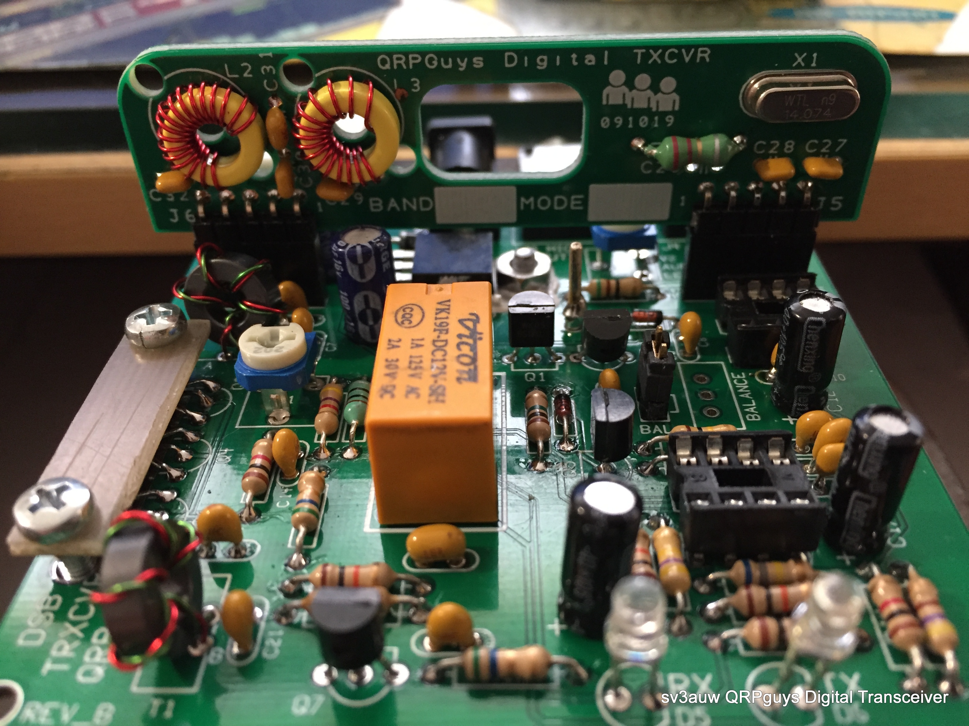
First on the construction bench sat quoting from their site:
"... The QRPGuys DSB Digital Transceiver is a low cost, multiband, DSB transceiver kit, currently with three easy plug-in band modules for 40/30/20m, (additional module pcb’s available). This transceiver is an evolution compiled from various DSB and digital designs on the internet from ZL2BMI, VK3YE, AA7EE, BD6CR, and others. With help from Jim Giammanco, (N5IB) and finally Steve Weber, (KD1JV), we are offering a transceiver with an approximate output of 2.5 watts on 40m, over 1.5 watts on 30m, and over 1 watt on 20m. The receiver sensitivity was measured at .4uV (-115dBm). All the components are included for the main board (3.0″ x 3.12″) and three (40/30/20m) band modules.

The transceiver will run the popular free WSJT-X software (Windows, Linux, or macOS) that requires an accurate time synchronization program, such as Dimension 4, or many of the other free ones available. Users will need two 3.5mm stereo jumpers to your computer or tablet microphone/speaker jacks on the sound card.


The transceiver’s internal VOX circuit will switch to transmit automatically when it senses an audio output signal from the software on the pc or tablet speaker jack. The connections to the transceiver are BNC for the antenna, 3.5mm stereo jumpers to the computer audio jacks, and 12-14 VDC for the pcb mounted 2.1mm pin coaxial power jack. Approximate power consumption is about RX-15mA/TX-350mA. The total weight w/band three modules is 3oz. (85gm). The normal tools required are a soldering iron with a small tip, rosin core solder, and small side cutters. The transceiver can be built in an evening. On a difficulty scale of 1 to 5, 5 being the most difficult, this is rated at 3 depending on your experience. Note also below, plans for building a 3.5″ sq. x 1.0″ high compact chassis from PCB material. ..."

This certain kit is retired now replaced by the Digital Transceiver II kit which has an optional Digital VFO board so the user can choose the Tx frequency and Tx Mode to bands from 160m – 17m.
It can easily constructed in one evening and in my Scale of Difficulty is a fair 2! As long as you are familiar with PCB soldering and toroid cores winding, is a piece of cake!
You can find the old version here but the newer and better is the one I strongly suggest to construct!
The kit I've constructed gave me 4W on 7.074MHz, 2W on 10.136MHz and 1W on 14.074MHz. Definitely not enough power to set alight the Ionosphere but more than enough to have a constant flow of qso's!
Enjoy your time and @staysafe
73 de sv3auw/m0lpt
No comments:
Post a Comment
Ονομάζομαι Τάκης Περρέας και αυτό είναι το προσωπικό μου ιστολόγιο, όπου “ιστολόγιο” το Δικτυακό ημερολόγιο!
Εδώ γράφω τις απόψεις μου, τις θέσεις μου, τις μελέτες μου και γενικά ό,τι έχει να κάνει μ' εμένα!
Δεν ζω από το ιστολόγιο, αντίθετα μου αφαιρεί αρκετό χρόνο από την καθημερινότητά μου. Δεν περιμένω να πλουτίσω λοιπόν ούτε από επισκέψεις, ούτε από “κλικ” σε σελίδες!
Με δεδομένη την ανυπαρξία σχολιασμού και ερωτήσεων, επιτρέπω πιά, μόνο σε μέλη να κάνουν σχόλια και ερωτήσεις. Στην περίπτωση που πραγματικά θέλετε να σχολιάσετε ή να ρωτήσετε, στείλτε ένα e-mail για να εγγραφείτε αυτόματα μέλος!
Κάντε όσες τεχνικές ερωτήσεις θέλετε και θα προσπαθήσω να απαντήσω σε όλες με τον καλύτερο και επεξηγηματικότερο τρόπο.
Αυτός είναι ο λόγος άλλωστε, για τον οποίο το ξεκίνησα (άσχετα αν μερικές φορές εγώ ο ίδιος ξεμακραίνω)!